Build day two is finally here and I have lots to report! Last Monday I received five Align DS520 servos for the helicopter and Friday I received the missing set screws for the washout guide. Also, Century advised that I did have the correct main shaft and the only difference between HD and LT was that LT uses a 4mm bolt on the main and HD uses a 5mm one. On Wednesday I took some time off work to go see my friend, Peter, fly his Radikal at TRAC. While I was there I got to meet some very nice people, see some, great flying, but most of all, I got a chance to get some perspective on what I was getting myself into…
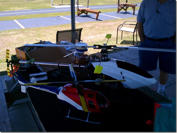
On the foreground is my BO-105 (on a 450 frame) and in the background is Peter’s Radikal G20. He did a great job and put on a good show flying it. I got to ask lots of questions and find out a few things:
-
- My DS520’s were too small… need to go with different servos.
- The servos I need are cheaper! Peter’s flying Hyperion DS20x-TMD on his cyclic, so I ordered a full set of five from www.heliflightcenter.com along with a programming adaptor (HP-AT-PRGUSB) just to see what I can do with it. The servos are fully programmable so I thought that would be fun to play with. This may come in handy with the throttle servo for speed, limits, etc.
- I’ll need two voltage regulators to feed my electrical needs (one for ignition system, one for gyro and receiver). I ordered two Castle Creations 10A regulators from www.ronlund.com.
- I’m planning on running 2x2s LiFe packs in parallel for additional current capacity and to act as ballast for weight & balance (one in front, one in rear). I’ll need two switches to fire up the flight electronics separately from the ignition system and I like the way Peter did his so I’m going to try and replicate it (sorry, no pics).
- The 6 mm hex starting wand system is fragile, a pull-starter would be advisable. (HW6118B is the mounting system and ZEN2634 is the pull starter. Picked them up from www.ronlund.com as well).
- Peter’s flying a converted 72 MHz radio to 2.4 GHz and doing well with it, I decided to go ahead and pick up the AnyLink system from Tactic and 3 receivers to replace the two in my other helis and take the fleet to the 2.4 GHz spectrum. I picked that up from www.towerhobbies.com which had a discount when ordering multiple receivers plus free shipping on orders above $100!
- The blades I need use a 5mm bolt to attach to the blade grip. This is not a very popular blade and it appears that RotorTech is the only one that makes them. Peter let me know of a program from Edge Rotorblades that will exchange crashed blades for new ones at a 50% discount. I sent in a couple sets of 325mm blades and requested some 623mm. They’re 4mm bolts but can be modified to run on 5mm blade grips.
- The sheer size of the helicopter is a huge advantage when it comes to visibility. I could see the helicopter clearly when it got further away and I believe that it will give me lots of confidence when I start flying mine.
Now that we got all that out of the way, on to the main event. I got to finish building the head and connect all of the links. I’m still pretty fascinated by the mixing setup on this head since I’ve never seen one like it. The size is still something I’m coming to terms with! I checked all link lengths and I’m hoping that the blades will track properly on the first try. I have no clue how to do the blade tracking on this setup but I’m sure it won’t be that hard to figure out.
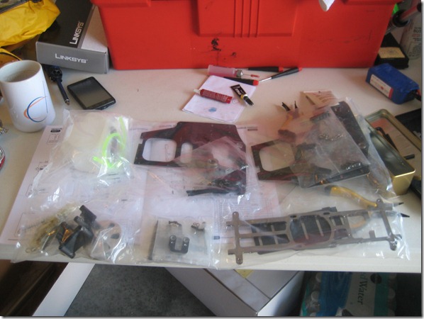
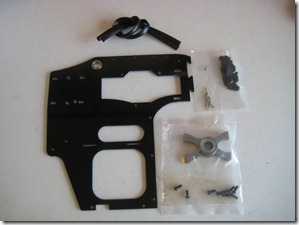
After the head setup was done, it was time to begin opening the first bag of the day. There was lots of cool stuff in it: gas tank, main shaft bearings, bell housing, etc. One of the most difficult things has been to keep track of items as opening the bags. For example, there are bags that contain screws that won’t be used until much later on in the build. This makes it easy to lose them so I recommend having some sort of a container to put them in, but don’t just throw them in there… make sure you sort them so you remember what you’re going to use them for.
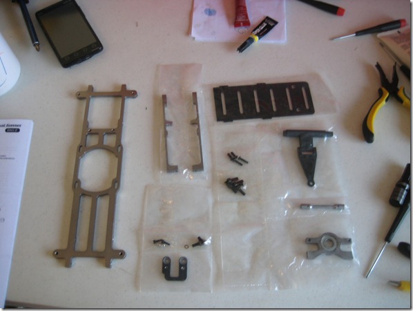
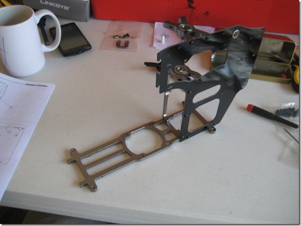
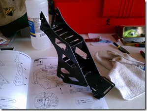
Today’s first building steps will be the main skeleton of the Radikal. We start with the bottom frame, some vertical supports and the bottom main shaft bearing. On of the smaller bags here gets used later on in the engine build to relocate the timing sensor from the factory position… more on that later.
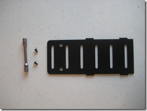
Main frame pieces… make sure you use medium thread lock on any metal to metal contact points, this is a prime candidate for screws backing out due to the engine vibration.
The finished product from this bag. Another sobering moment with regards to the size of the finished product. Some of you reading this may fly larger helicopters so this is nothing to you… I’ve been flying 450’s for over 6 years, this is literally a HUGE deal for me!
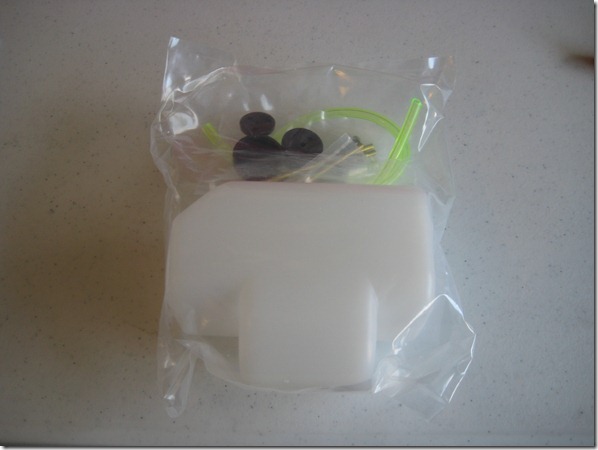
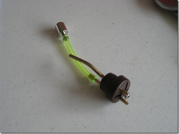
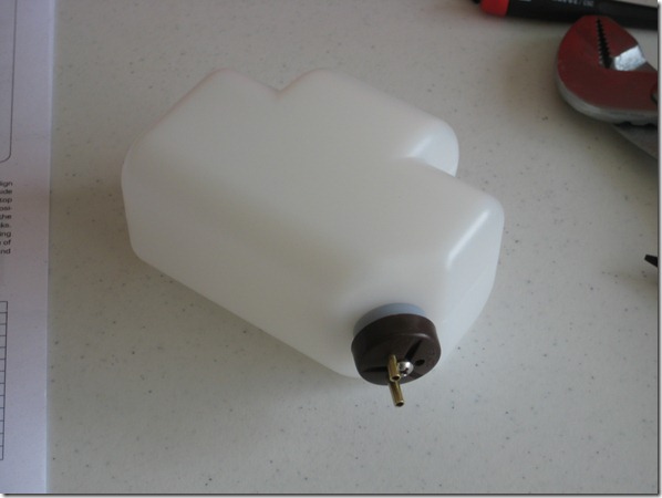
Next, I tackled the gas tank. Looks pretty simple, right? Well, I had to bend copper to get this step done. I think a little background on me is helpful here… I’m pretty much an indoor human, I don’t typically build stuff and I don’t consider myself handy. Here I am, with some copper tubes and I have to bend them, so what do I do? I go to YouTube and look it up! So first, the gas tank bag:
Next, the YouTube video on bending copper:
And finally, the finished product:
Before you go crazy telling me that I did it wrong and the vent tube is facing wrong or whatever, I fixed it when I finally got it all put together.
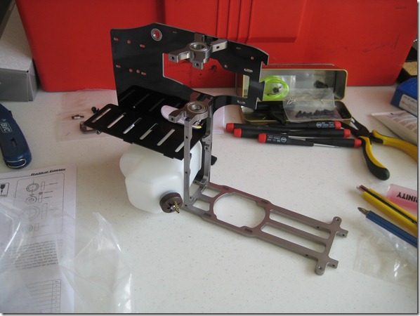
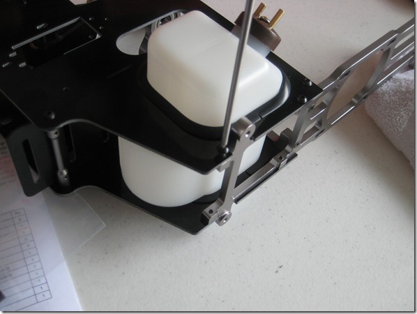
Test fit in the frame:
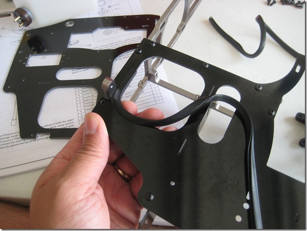
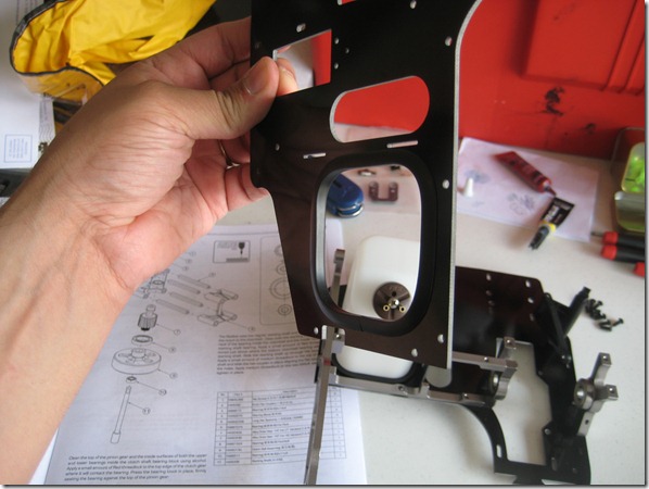
Then the gas tank isolation rubber molding stuff (not sure of the name but the manual called it something like that).
I should also stop here to accentuate the fact that I am blowing myself away with the care and actual craftsmanship that I’m exhibiting here. Anyone that knows me, knows how careless I am putting this type of stuff together just so I can go out and fly. Don’t get me wrong, my aircraft are safe, they just may not look very good.
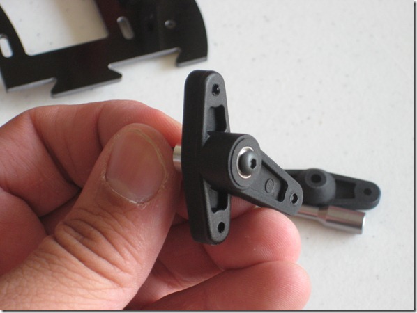
I’m not sure why I took this picture but it is one of the bell crank arms for the swash plate/servo mechanism.
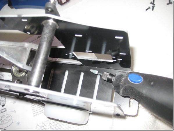
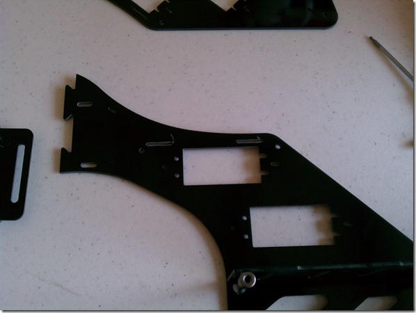
Here’s a good tip… listen up! Test fit your electronics trays BEFORE you bolt stuff down. Some of the openings for the notches will need to be opened up a bit with a rotary tool before they will fit snugly in there. I did not know this… it caused me great frustration for extended periods of time!
Another tip… there are not enough screws to go back here. One page on the manual doesn’t say to use one (left side) the other page says to (right side). In the end, there were not enough screws so don’t put one on either side.
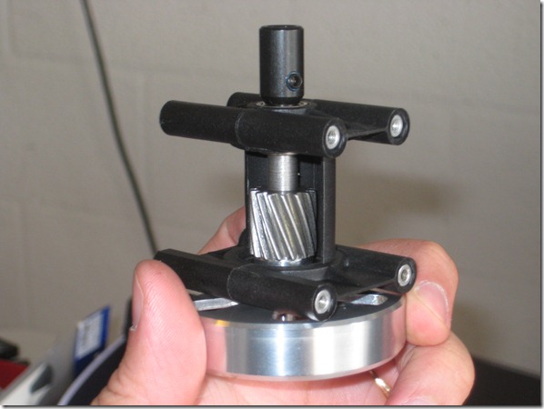
Next, I assembled the clutch bell and starting adapter assembly. The clutch has a one-way bearing so you won’t need a starter with one. Here’s where it got interesting, the manual says that this whole assembly is considered a wear and tear item with regards to starting (the clutch will wear as well). They recommend a pull-starter for your first flight of the day and then electric for subsequent ones. After seeing how this was all put together, I decided to heed Peter’s warning and just spring for the pull starter. I don’t plan on starting this with an electric starter so it is a decoration for now.
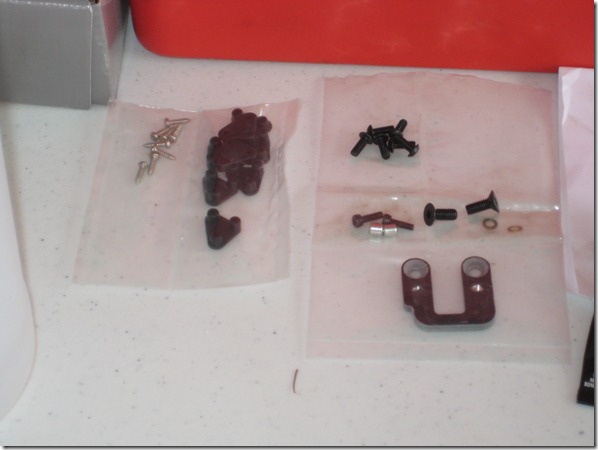
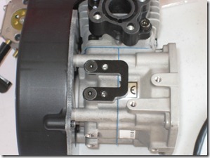
This is here to remind me of leftover parts. The bracket you see gets used later on with the engine build to re-locate the crank position sensor for the electronic ignition.
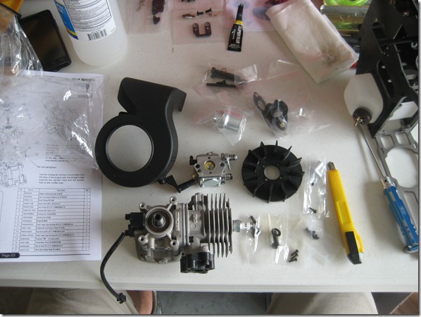
Behold, the Zenoah G200PU engine in its naked glory. Al over at B.H. Hanson already stripped the un-necessary parts from the engine so I got to skip that step. He also somehow affixed the crank key so no worries about losing it.
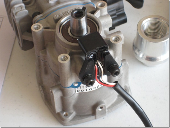
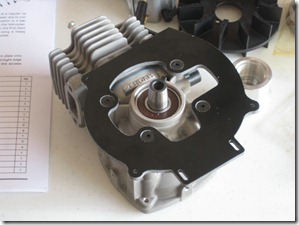
Step 1: REMOVE THE IGNITION SENSOR… I REPEAT, REMOVE IT!!!! The manual makes no mention of this and when I tried to install the support backing for the fan shroud it puzzled me for a few minutes. Save yourself frustration and trust me on this one. It doesn’t even get mounted in the same place when we’re done.
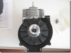
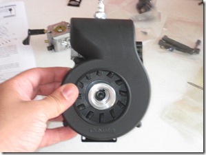
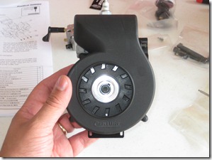
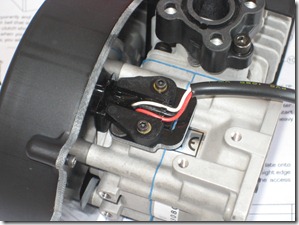
So the engine is coming together quite nicely. There’s something about matching the magnets on the fan to the sensor. To be honest, since I didn’t take the original engine apart I have no clue what to do here so we’ll have to figure it out when starting time comes. At this point, the assembly reminds me of the Robinson R22’s fan assembly! At this point, we can re-mount our ignition sensor. Note that we use a bracket to relocate it and we mount the sensor right on it. Don’t forget thread lock! Another tip from Al was to observe the back and forth play on the crankshaft and make sure the sensor would be free and clear of it no matter what the position.
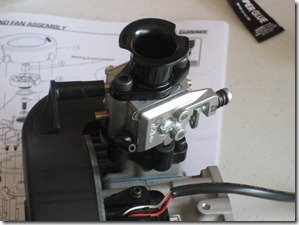
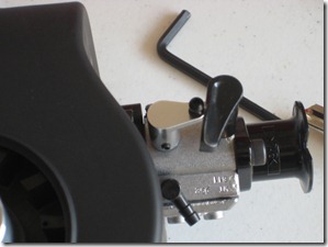
Carburator time! A note on the throttle ball… the screw is small, the manual says don’t overtighten: IT MEANS IT!!!!! I stripped mine but I think there was enough thread in there to rescue it with heavy thread locker. I’m going to let it set overnight and check it out tomorrow but I may already have to replace this. If I have to, I’m going to explore alternatives because it seems way too fragile to me.
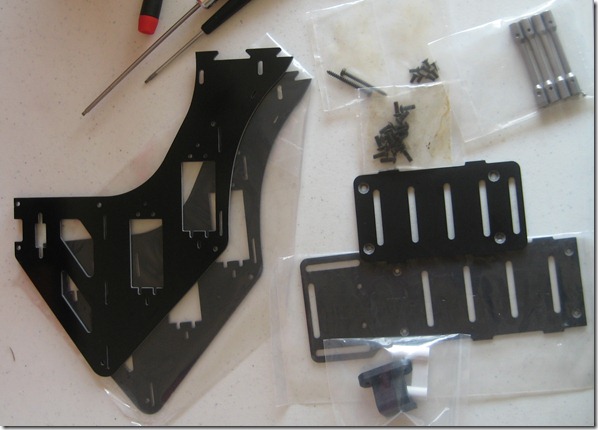
Now we get to open up another bag, this time it is the forward frame parts and two electronics trays. I wish I had this much room for electronics on my 450’s!
The same suggestion applies here regarding the rotary tool. I slipped a few times, hence the scratches, but this is on the inside and no one will see it. I only had to enlarge the top slots but after it was done, everything fit quite nicely.
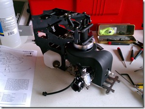
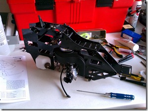
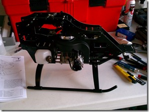
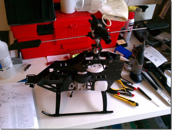
The next few shots show the forward frame assembly completed, the engine mounted, rotor head mounted, and the frame finished with the skids on. Here are my pieces of wisdom:
-
-
- Take your time
- Do not tighten any of the engine mount points all the way, you’ll need to slide them around later.
- Do not use screws yet with the clutch bell assembly, wait until the two frame halves have been fit together and the notches are perfectly lined up.
- Don’t install the top forward electronics tray’s aft screws until you’ve fit the front half of the frame with the rear half. You’ll need them off so you can spread the front frame notches over the rear frame notches. This will not make sense until you’re actually doing it! The instruction manual doesn’t help with this either.
- When mounting the rotor head, I recommend removing two screws from the top main shaft bearing block on the same side of the helicopter. This will give you some extra wiggle room to install all the bearings and spacers that make up the main gear setup. Also, this was a huge PAIN. There is a washer on the bottom that you have to perfectly align in order to get the main shaft to go all the way through. Once you’ve gotten the main shaft all the way through, tighten the screws to the top main shaft bearing block. This should sandwich everything together and make it a little easier for the next thing, the retaining pin that locks the one-way bearing to the main shaft. I used a hex driver that was a similar diameter to the pin (except a hair smaller) and pushed it all the way through. I then forced it out with the main pin (pounding it with a nut driver part of the way and with a hex driver the rest of the way). Don’t go too hard on it or it will come out the other side and you’ll have to start over. Also, don’t forget to tighten the collar screw… I did and now I have to go back out to the garage to do that before I forget!
-
- After all that, here’s the end result!
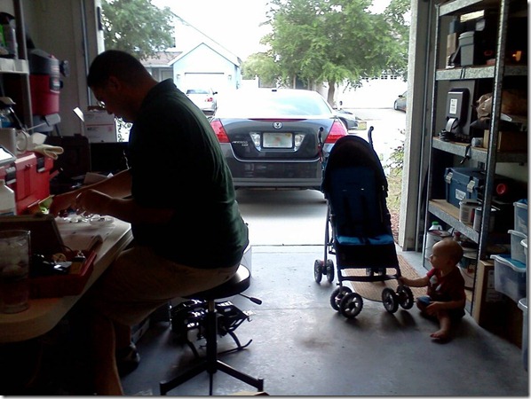
Conclusion: I enjoyed building the helicopter and I even had some help! This was the most time I spent on the Radikal in one sitting yet, I think altogether it was around six hours. I’m taking my time, not rushing, not cutting corners, and enjoying the process. If you’re building one or own one, let me know how things are going with yours!
