-
-
- The wrong clutch shoe shipped in the box: Century sent me the correct clutch bell for the HD model (performance clutch bell) but the incorrect clutch (standard clutch) so there was a sizable gap between the bell and shoe. I called Century and they volunteered to send a new clutch bell. At that point, I was under the impression that the performance set was an upgrade but later found out that it comes standard on the HD. I called Century back and they will be sending the performance clutch shoe and I’ll ship both the standard clutch bell and standard clutch shoe back to them.
- I got the wrong cyclic servos: So I thought I was ordering five Hyperion TMD servos but instead I got the GCD servos. Here’s the difference: the TMD’s have more torque but less speed and the GCD’s have less torque and more speed. Since I’m going to use a governor, I can keep the GCD’s for the tail and engine since speed will be helpful in both of those applications. I’m in the process of contacting HeliFlightCenter to get some servos exchanged.
- The engine break-in may shake the helicopter to pieces: since break-in will be rough, it could be harmful to the engine. I’m in the process of finding a location (since my neighborhood may not take too kindly to running a 2-stroke engine to speed) and a method to break-in the engine out of the helicopter.
- Mufflers are expensive: the stock muffler is $8, the Century muffler is $150. I’m going to play around with the stock muffler until I’m confident I won’t crash. At that point, I’ll upgrade the muffler. Stock mufflers for the Zenoah will need to be modified to direct the exhaust away from the gas tank; I’ll post more info regarding muffler modification once I get to that point.
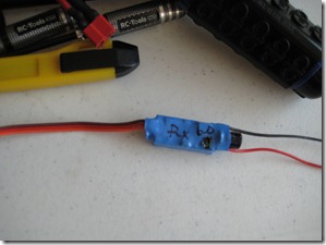
- Voltage regulators by Castle are pretty sweet: the 10 amp voltage regulator is nice because you can tune the voltage in 10th volt increments. This allows me to run a precise 4.8 volts for the ignition system, 6 volts for the receiver, and straight battery voltage from the 2s packs for the servos. Bad news though, I burnt one up and it took the receiver with it. Not really sure what happened but more on that later.
- Futaba GV-1’s go for cheap on eBay: the title is self explanatory. I made the governor decision after much deliberation. The last thing I want here is to bust up my engine by redlining it when I unload the main rotor in flight. This is very inexpensive insurance against that… but another part to tune. I’m sure we’ll get to explore the wonderful world of governors later.
- My stator gator has the wrong plug: I’ve contacted them about this but no word yet. If I don’t have any luck with it, I may just splice it and be done with it.
- Edge Rotorblades (623 mm) use 4mm bolts: But when you remove the bushing, they’re 5mm. My friend Peter is test-flying them this week, hopefully they hold up. I’m planning on drilling out my blade grips to 6mm if I can find a bushing that will reduce the diameter to 4mm so I can use 4mm bolts. Why all the trouble? The right blades are $120/pair, Edge’s blade replacement program gets me two sets for $90. You do the math!
-
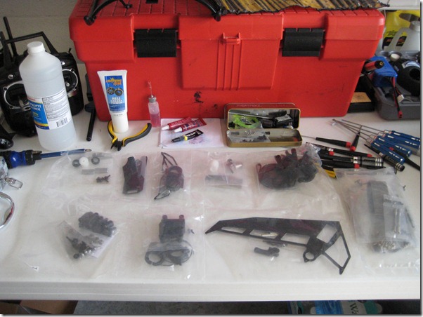
Enough learning, on to the building! The first bag of the day begins the tail rotor assembly.
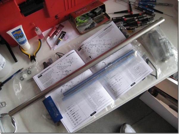
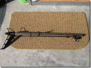
Comparison of the 450 boom and the Radikal’s… there is NO comparison!
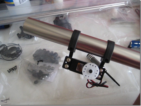
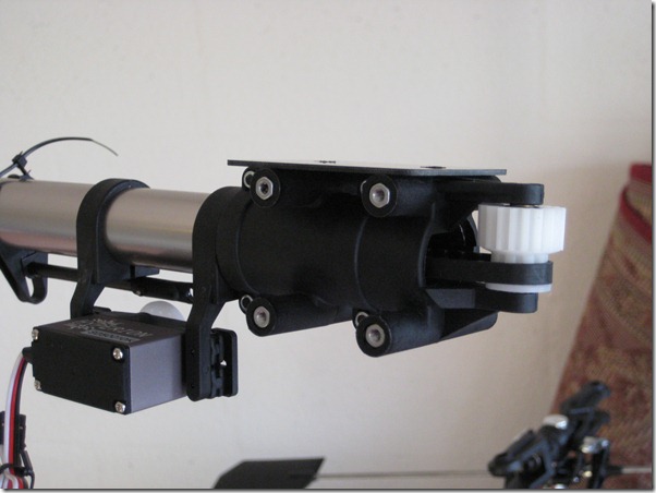
I loosely fitted the servo on the boom. Later on in the process, I ended up turning the servo around (horn-side towards the helicopter) since it fit better with the push rod.
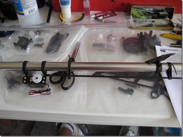
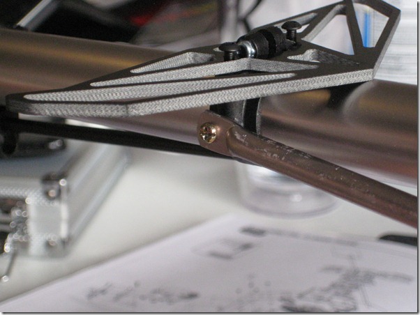
The horizontal stabilizer, and push-rod guides go on now. Looking back on this, I would have left the actual stabilizer for last so I could adjust the tension on the mount once the stabilizing rods were installed.
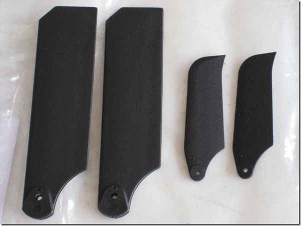
Tail rotor blade comparison between the Radikal and the 450.
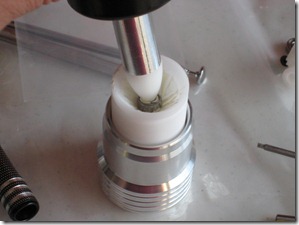
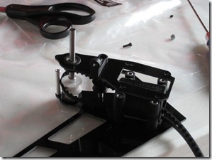
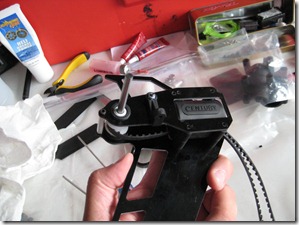
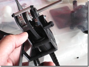
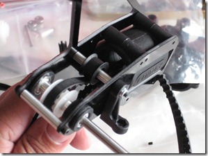
The tail rotor gear case comes together. I had to use the Dremel tool to enlarge the bearing holes. I also used a bearing greaser tool (“The Greaser” Bearing Greaser) to remove the factory grease from these bearings and replace with the Heli Grease Power Lightning Lube from Boca Bearings. I didn’t do this on the main rotor bearings because I didn’t have The Greaser yet plus that’s going to be a relatively lower RPM than the tail rotor. Next time the main gear bearings are out, I’ll grease them up! Here is a series of pictures of the tail rotor assembly being put together.
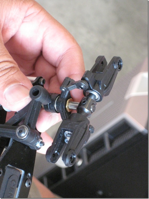
This is where you will want to pay attention… make sure you sand the paint off the steel balls. This will make the pitch slider slide smoothly. Also, the diagram in the manual is not very clear about a set screw that goes INSIDE the tail rotor shaft to set the pin that connects the pinion to the shaft. Make sure you use that set screw otherwise the pin will fly out! The set screw goes in on the left side of the shaft (not the tail rotor side).
Next, make sure you put the belt around the front pinion BEFORE mounting it to the plastic frame. It will save you time!
Looking good… and HUGE!
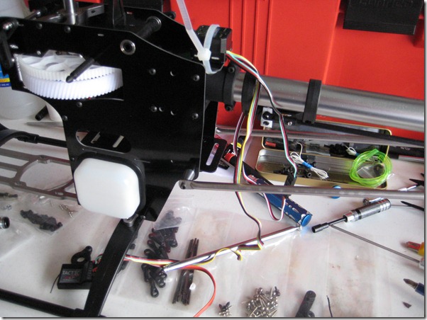
Those “mystery missing screws” from Day 1 now make sense.. I had to move them down to make room for the tail boom stabilizing rods.
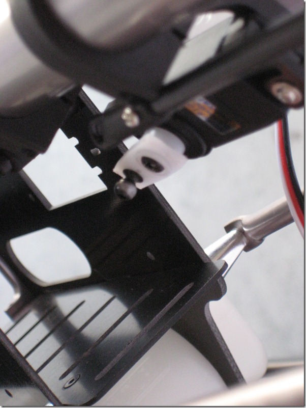
The servo ball was also painted steel so I sanded it. Also note the the servo horn was cut down to size so it would not strike the servo support as well as moved so the horn side would be closest to the helicopter. I tested the servo and tail mechanism with the receiver, it all moved perfectly!
I went to install the tail boom support rod and the head of the factory screw just came off. I replaced it with a spare and went on my way.
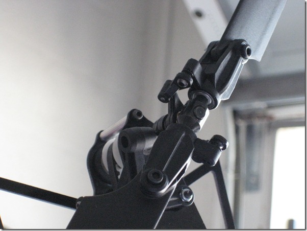
Assembled tail rotor. Take your time with all of the thrust bearings and heed the warnings in the manual regarding the plastic shavings from forcing the bearings into the grips.
The gyro is temporarily installed for testing.
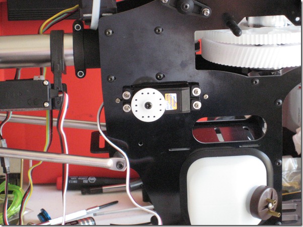
One of the GCD servos in place for the collective. I made the decision to get the TMD’s after this picture was taken.
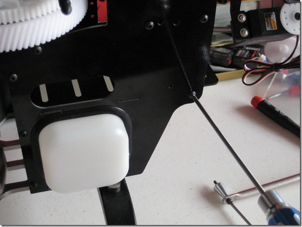
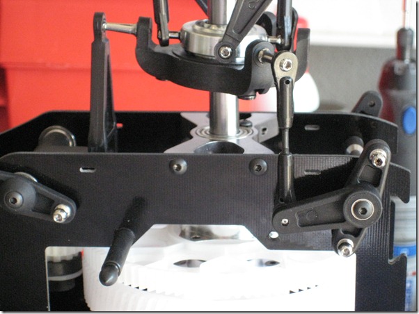
Swash plate control rods are made and installed. Be precise!
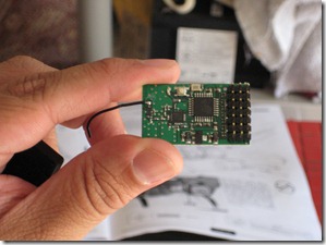
Finally, the burnt up voltage regulator and receiver. Not sure what happened but I hope it doesn’t happen again. By the next time I’m building, I should have the 2s packs and some extension leads so I can build the electrical system to “production” specs and not risk overloading the regulator. I don’t think that’s what happened here but I want to make sure and avoid it next time.
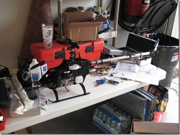
CONCLUSION: Everything looks great so far! You may have noticed the front half of the helicopter and the engine missing in some of the last pictures… I took them off to get the engine ready for break-in and the clutch replaced. Thanks for following this build, I hope the tips here help you on your own journey!
One more thing… Century has videos on building the Radikal G20. They don’t follow the order in their manual… food for thought!

